Submerged Rocket
- Sep 13, 2025
- 7 min read

I've always liked rocketry, made and launched plenty of Estes model rockets when I was younger. So when I heard one of my robotics mentors, Joe Duva (who happens to be a head engineer at JHU APL) made custom rocket motors, we decided pretty quick to do a project of some kind together. One that would teach both of us new things and do something out of the ordinary.
So during the Summer of 2025; Joe, Ananya Shah (a friend and robotics teammate of mine for many years), and I decided to launch a custom rocket from underwater. The inspiration for the idea is obvious, but what drew us to it was the engineering challenge. Obviously, a rocket motor that relies on combustions doesn't like water very much. But other issues arise. The drag caused by water is greater than air, breaking through surface tension, water "dissolves" cardboard rocket bodies, and (we didn't figure this one out until launch) the motor flames would burn through a plastic enclosure.

We started by defining requirements. The primary ones being stable flight (must consistently fly, within tolerance of, vertical), reusability (must be recovered after each launch to be prepared for another), must launch through, and must maintain stable flight after leaving the water.
We quickly decided on an enclosure or launch vehicle to protect the rocket before launch, and guide the rocket during. Which lead us to classify four subsystems. The motor, the electronics (to ignite the fuel), the rocket body, and the launch vehicle.
It's worth noting that we considered making the vehicle mobile or floating. But we decided the time limit was too stressed to make this a reality, so this was put on the side as a possible later project.
So we moved forward with a plan, a 3D printed launch tube with slits that would guide the rocket via the fins, a 3D printed plastic rocket that would be water-resistant and could be iterated easily, and a motor that could be wired directly to the controls or indirectly through a receiver.
For the motor, we quickly decided to use standard A-sized motors from Estes. These were chosen because of the predicted size and approximate weight of the rocket. Additionally, custom motors are would add an extra point of failure and inconsistencies. Though, we spent a few days to make and test custom motors. We simulated possible designs in a program called Open Rocket to optimize the thrust based on the fuel and motor diameter. We used Joe's personal grain composition that he had developed through his years of practice. These were used to test water-proofing the engines directly with wax.

Then came designing the physical body of the rocket. We considered overall size, inner diameter, space for a recovery system, and how stable it would fly through water and air. We simulated these factors, among others, in Open Rocket. To simulate flying through water, we increased the "air density" to approximate the effect the water would have on the rocket's flight. Eventually we ended up on a 4 finned design with a detachable nose cone.

Preventing water from entering the motor was obviously a top priority. While the tube would prevent most of the water from entering, the tube would still need to open for the rocket to pass through. We came up with a three-phase design. Firstly, a gate or valve would be closed prior to launch. Secondly, as the gate/valve opened, we would shoot pressured air through the launch tube. This air would push water out of the tube, but it would also solve two more of our issues, the surface tension and the change in surrounding density. By pushing air through the water, this disrupts the surface tension of the water and lowers the density (and therefore the change in density between the water and the air), causing a more stable and consistent flight path. Lastly, the rocket and motor would be sealed with wax, this was a last line of defense that would be reapplied with each launch.

We had three concepts for the gate/valve, the first of which was a simple hinged door. While this was the simplest option (at least mechanically), it left much to be desired. We were worried that a servo would not have the torque to open it under the pressure of the water, also the design had the longest delay between the start of the opening sequence (letting water in) and the launch tube being clear for the launch. For these reasons, we decided against a motorized door.
The second was what we called "supported foil". The idea was to use a foil or wrap as a membrane to between the tube and the water. The membrane would tear as the rocket goes through (the tip of the nose cone is pointy), but we were worried about a free-flowing membrane not tearing uniformly and disrupting the stable flight of the rocket. Because of this, we designed a cap with four "arms" to control the shape and tearing pattern of the membrane. It would also make mounting a new membrane easier after each launch. While this would be a very simple and entirely passive design, it wasn't as impressive as we wanted it to be and wouldn't be a challenge, hence this was labelled as a back-up solution.

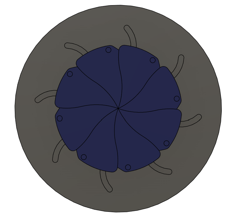
The third and chosen design was an iris valve. You may not know the term, but you definitely have seen them on camera lenses or in movies. These use pivoting petals that are jointed together to keep a constantly opened radius. This design had the majority of the features we desired, except it was the most complicated by far. So we took on the challenge, using the supported foil design as a back-up plan.
As there are multiple variations of iris mechanisms, I designed and 3D printed 2 intitial prototypes. One "slotted" and one "virtual armed"
The tolerances on the slotted design caused some manufacturing and operational issues. Hence, the virtual-arm design was favored, and I moved forward with a sealed version that used TPU rings and slots to minimize the gap that water can breach through.


Ananya (as the computer specialist in the group) worked on the electrical subsystem. This included the igniter, the input, and a planned wireless system to launch the rocket from a distance. The circuit used Weemo boards that were connected, one to the input and one wired to the igniter. They would send a signal to a relay which would power the igniter and light the motor. Sadly this wasn't completed in time to be integrated, but the prototype was fantastic. For the test launches, we would use the COTS Estes igniter.
So we had the parts we needed, so naturally we needed a base to mount all of them. The launch tube was designed to hold everything together, guide the rocket to a vertical path, protect the rocket from the majority of the water, and house the igniter leads. This is how we came up with a three-piece tower, each section is threaded together with a TPU o-ring to seal it. The lower section is a base and cap so we can access the igniter leads. The middle section contained the supports for the rocket prior to take off, and the upper had the guide rails and mounting holes for the Iris valve.

To test the seals, we put paper towel pieces at key points (ex. each opening and each stage), then wrapped duct tape on each opening to control the number of variables. The tower was then left to soak in a bucket for 10 minutes. Based on the amount of water in the tower and which towels were wet, we came to two possible conclusions. The towels at the openings and the ones on the inside of the lower stage were soaked. So either the seals broke or water got through the walls of the tube. We believe water diffused through, as we found the structure was water-logged.

The solution to this would be reprinting the tower in with a filament with better layer adhesion, like PETG or TPU. This would take a lot of time and cost more than preferred, hence we made the call that it would work despite this flaw, as the water concentrated in the lower stage (beneath the motor).
With that test and every component complete, the time had come for launches. We sadly didn't have a tall enough bucket to test the full system for this test, so made the decision to flood the launch tube, trusting our secondary and tertiary systems to keep the motor dry. We also didn't make the lower lip of the tower large enough for weights so you'll see rocks on the valve.


So we hooked up the system, sealing the gaps and setting up the motor pressure fit to the perfect tolerance. We had six attempts, four of which the motor got stuck in the base (blasting the rocket out separately), one of which where the compressed air accidentally pushed the rocket out of the tube, and (with our final A-sized motor) a beautiful launch.
This worked beyond expectations, launching a few hundred feet into the sky. The flight was stable, the nose cone separated, and nothing broke. However, there were a few interesting observations throughout the launches. First of all, the tower was water-logged, partially because the motor getting stuck blasted a hole into the lower cap of the tower. Though, this led to another observation that the water flooding into the bottom actually helped prevent the plastic from melting completely.

This project was much more educational and exciting than any of us predicted. I learned aerodynamics, propulsion chemistry and mechanics, some fluid dynamics, systems engineering, and how to make the minimum viable product to meet time and cost deadlines. This was of course a very fun project and a great way to wrap up my last summer before college.
If we were to continue this project, there's definitely some changes we would make. First of all finishing the electronics and mounting a motor to the iris valve. This would make the project much more impressive and multi-faceted, this would also allow us to test in deeper waters. We'd also reprint the rocket in PETG-CF (water-resistant and stronger) and the tube in transparent PETG (water resistant and monitoring).
This was a very fun project and I may be doing more rocketry at UMD.
Thanks for reading!
Austin


